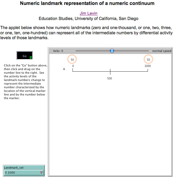
Figure 1: An web file that shows a representation of the number 500 with equal activity levels of landmarks "0" and "1000".
James A. Levin
Education Studies
University of California, San Diego
URL for this paper: http://pages.ucsd.edu/~jalevin/landmark-mediation/landmark-mediated-geometry.html
In a landmark mediated geometry described in this note, continua are defined by discrete landmarks, with intermediate points defined by one or more landmarks being simultaneously active. The specific intermediate point is determined by the ratio of the activity levels of the landmarks. For example, if two landmarks are both simultaneously active and have the same activity level, then they define the point halfway between the two points. If one of the landmarks is twice as active as the other, that defines a point one third of the distance from the more active landmark and two thirds of the way from the less active landmark. In this way, the entire continuum of points is defined by the differential ratio of multiple simultaneously active landmarks (Levin, 2009). Figure 1 shows two numeric landmark concepts ("0" and "1000") which have equal activity levels (50). This represents the number halfway between them, 500.
Figure 1: An web file that shows a representation of the number 500 with equal
activity levels of landmarks "0" and "1000".
If you click on Figure 1, you will be able to interact with an web file that illustrates this "landmark representation" concept. web files are small applications that can be run over the web that allow the reader to take an active role in exploring the dynamic nature of the concepts in this note. The web files were created in NetLogo (Wilensky, 1999), a powerful multi-agent modeling environment that is cross-platform, freely available and allows simulations to be saved as HTML5 Web files that can be accessed via the Web. In each case, if you are reading this paper through the web, you can click on a link or figure to start up one of these web files. The web files are large and so may take some time to load. If you are reading this paper in print format, you may want to access the web version at the same time (or at some point, if it is not possible right now) and try out the web files.
Once the web file starts, select (click on or touch) the "Go" button, and then drag the marker line to see the changes in the activity levels of the landmark concepts that represent the marked point.
A simple line segment. A line segment is defined by three spatial landmark components, two end points and a mid point.
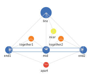
Figure 2: A landmark mediated representation of a simple line segment.
There are two kinds of mediators among these three landmark component concepts. There are two "together" mediators, one between each end landmark and the mid landmark. Each "together" mediator operates to move each of its parameter concepts spatially in the direction of the other parameter concept. There is an "apart" mediator between the two end landmarks. This "apart" mediator operates to move each of its parameter concepts spatially in a direction opposite of the other parameter concept.
These two kinds of mediators operate simultaneously to produce the linearity of the line segment. Click on Figure 2 to see a web file that implements this mediational process, which results in Figure 3.
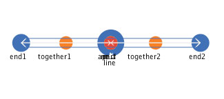
Figure 3: The resulting line segment after the operation of the mediators.
The global property of "length" of the line segment is a balance between the relative strength of the "together" mediators and the "apart" mediator. The stronger the attraction of the "together" mediators, the shorter the line segment. The strong the repulsion of the "apart" mediator, the longer the line segment. The resulting length is a dynamic stability global property of the simultaneous operation of all three of the mediators.
This landmark mediation framework for a line segment exhibits the dynamic properties of "self-repair:" and "self-organization". If one of the concepts is translated so that the spatial layout is no longer linear, the mediators will all act simultaneously to "self-repair" the linear global property. Similarly, if all of the concepts that define a line segment are randomly "scrambled" (with each placed in a random location), the simultaneous operation of the mediators will operate to "self-organize" into a linear spatial organization. In all of the cases of global properties (length, self-repair, self-organization), the global property is accomplished with the simultaneous operation of lower level mediators.
The details of the mediators between the component landmarks can be "hidden" inside this simple line segment, as shown in Figure 4.
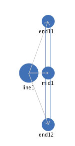
Figure 4: A simple line segment with the internal mediators not shown.
To interact with this representation, click on Figure 4 and select "simple line segment" from the "Which_shape" selection box. Just like the more explicit representation of a simple line segment shown in figure 2, this simple line segment self-repairs and self-organizes - the only difference is that the "internal" mediators that accomplish that are not visible. The purpose of this simpler display is so that we can now move to a higher level of shapes, in which these simple line segments become components themselves of a more complex shape.
A triangle. Now with simple line segments like those shown in Figure 4, we can now construct somewhat more complex figures. By using three of these simple line segments and a "near" mediator among the end landmarks of different of these segments, we can define a triangle, as shown in Figure 5. "Near" is like "together" in pulling its parameters together, but it pulls much more strongly.
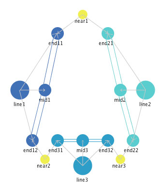
Figure 5: A triangle.
To interact with this representation, click on Figure 5, and select "triangle" from the "Which_shape" selection. Click on the "Go" button to see the operation of the mediators. After the operation of the three "near" mediators and the mediators "hidden" inside the line segments (those shown in Figure 2 but not shown in Figure 4), the result is shown in Figure 6.
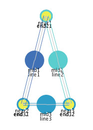
Figure 6: A triangle after the operation of its mediators.
Like the single simple line segment shown previously, this triangle has the global properties of size, self-repair, and self-organization, all generated from the simultaneous operation of the multiple mediators that define the shape. The "near" mediators pull the ends of the line segments together, while the "hidden" mediators that constitute each line segment operate to maintain the linearity of each line. The shape of the triangle is defined by the relative lengths of its line segment components. In the triangle shown in figures 5 and 6, the lengths of line segments 1 and 2 are equal, and the length of line segment 3 is shorter. This relationship of line segments creates the isosceles triangle shown in figure 6. If you click on figure 6, you can interact with this triangle. Select "triangle" from the "Which_shape" selector and click the "Go" button. If you move one of the components of the triangle, you will see it self-repair into the triangle. If you click on the "Scramble" button, you will see all of the components placed in a random location and then the mediators operate to self-organize back into the triangle. One thing that you will notice is that this definition of a triangle is independent of orientation. So while the shape will self-repair and self-organize into the same triangle, that triangle will may well have a different orientation. How do we define a triangle as having a specific orientation?
Orientation. We can define a shape as having a specific orientation by adding an orientation mediator. Figure 7a shows the definition of the isosceles shown in figure 5 and 6 with two additional orientation "above" mediators specifying relationships between the juncture of the two equal sides and the ends of the shorter side.
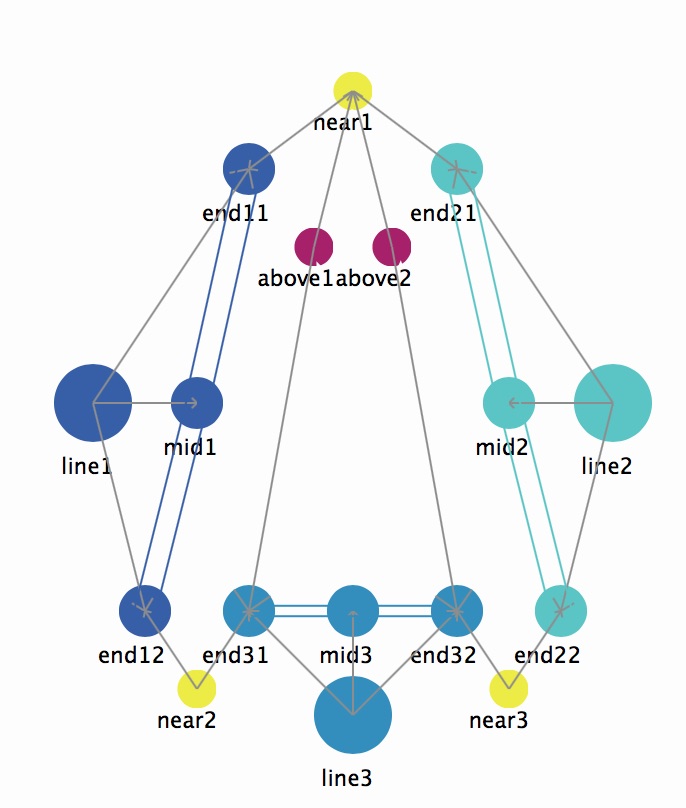
Figure 7: An oriented triangle.
If you interact with this triangle, you will see that if this shape is in an orientation different from that specified by the "above" mediator, the orientation mediators will operate to change the orientation. If the shape is in the specified orientation, the "above" mediators will operate to maintain that orientation.
A more complex line segment. The simple line segment defined above had three landmark components, its two end points and its mid point. A line segment can be defined with more landmarks as well. Figure 8 shows a more complex line segment defined with five landmark components, the three contained in the simple line segment definition and two additional landmarks intermediate between the end points and the mid point.
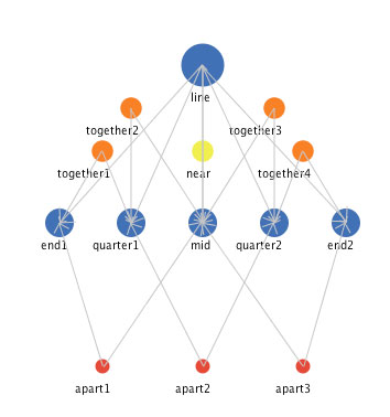
Figure 8: The representation of a more complex line segment.
The mediators of this more complex line are the same as those of the simple line defined above. The difference is that there are more mediators. There are "together" mediators between each of the adjacent landmark components of this more complex line, and there are "apart" mediators between every other landmark component. You can click on Figure 8 to interact with this representation. Figure 9 shows the state of the complex line segment after the mediators have operated to create a dynamically stable state.

Figure 9: The dynamically stable state of the complex line
segment.
As in the case of the simple line segment, we can "hide" these "internal" mediators, to show the complex line segment in a simpler way, as shown in Figure 10.
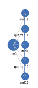
Figure 10: A simplified display of a more complex line segment
You can interact with a representation of this more complex line segment by clicking on Figure 10 and selecting "complex line segment" from the "Which_shape" selection list.
This more complex line segment has the same global properties of size, self-repair, and self-organization as the simple line segment. But it has an additional property of bendability. This is best illustrated when one of these more complex line segments is combined with a simple line segment, as shown in Figure 11.
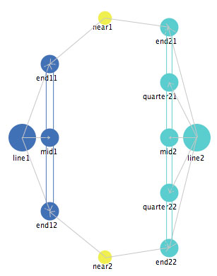
Figure 11: The representation of a simple and complex line
segment.
When the mediators of this combined shape operate, the dynamic stability shown in Figure 12 is reached. To interact with this representation, click on Figure 11 or 12 and select "simple&complex line segment" from the "Which_shape" selector.
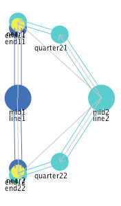
Figure 12: The dynamic stable state reached after the operation
of the mediators.
The global property of "bendability" allows the more complex line segment to serve as an approximation of a curved line segment. The more complex the line segment (as defined by having more landmark components), the closer the approximation. The intermediate points on the curve are represented by differential activity levels of landmark components, just as in the case of the straight line segment shown in Figure 2.
Angles. How are angles represented in this landmark mediated geometry? As in other geometries, an angle is the junction of two line segments. In this framework, we create a junction with the "near" mediator, impacting the "end" landmarks of two line segment, as shown in Figure 13.
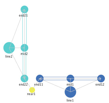
Figure13: Two line segments conjoined to form an angle.
Once you interact with this representation (which you can do by clicking on Figure 13 and selecting "pivot" from the "Which_shape" selection set), you will find that it is a shape that can take on any angle. That is, the ends of the two line segments are conjoined by the "near" mediator, but no particular angle is specified, so the two line segments can "pivot" around to form any angle. Some of the possible stable states of this "pivot" are shown in Figure 14.
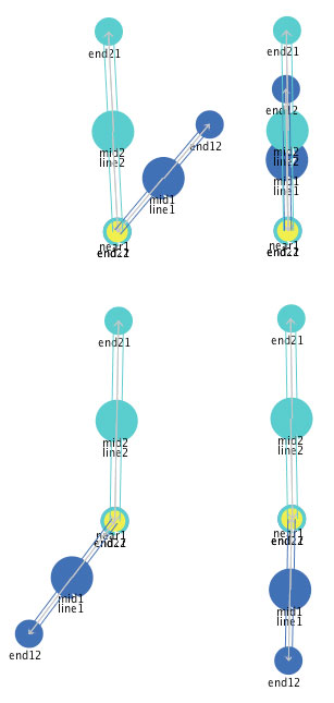
Figure 14: Four of an infinite number of stable states of the two conjoined
line
segments.
So how can we define a fixed angle? One way to do that is shown by the representation of a triangle above. By creating a triangle with a particular ratio of lengths of the component line segments, we can create any desired angle. Suppose we wanted a right angle. Figure 15 shows a right triangle, which creates (and maintains) a right angle as one of its three angles.
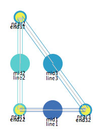
Figure 15: A triangle containing a right angle.
Invisible line segments. Suppose we wanted to create a right angle that stood alone, not part of a right triangle. To do this, we need to introduce a new element, which we will call an "invisible line segment". This is analogous to the construction lines used in geometric proofs, in that it is a constraint on the geometric figure without being a component of the figure. Figure 16 shows a right angle created (and maintained) through an invisible-line mediator.
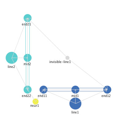
Figure 16: A right angle supported by an invisible line segment
mediator.
We can use this same "invisible line segment" construct to create a freestanding approximation to a curved line segment, as shown in Figure 17.
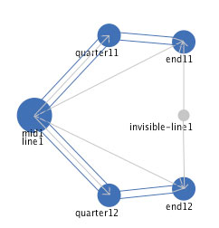
Figure 17: An approximate curve segment, created using a complex
line segment and an invisible line segment.
In fact, we can use these invisible line segments to construct more complex approximations to curved line segments. One such complex shape is shown in Figure 18.
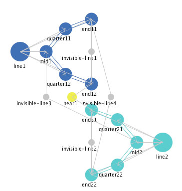
Figure 18: A double approximate curved segment.
In this figure, there are two invisible line segments ("invisible-line1" and "invisible-line2") that create the approximate curves by pulling the end points of complex line segments together. There is one invisible line segment ("invisible-line4") that keeps the two approximate curves from folding over on each other. What function does the last invisible line segment ("invisible-line3") serve? Through its mediation, it keeps the two approximate curved segments on the opposite sides of the vertical axis. If that invisible line segment were shorter, the same representation would change to a shape that had both approximate curved segments on the same side. You can see this by adjusting the slider in the web file shown in Figure 19.
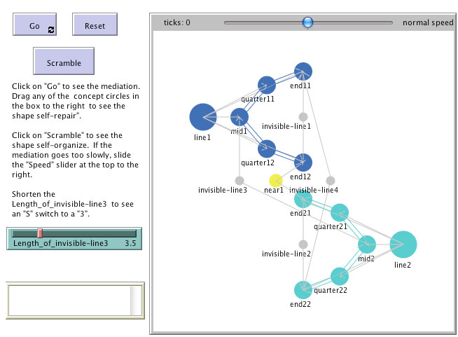
Figure 19: A double approximate curved segment that reorganizes
when the length of an invisible line mediator shortens.
Click on figure 19, then when the web file appears, click on the "Go" button and watch as you slide the "Length_of_invisible_line3" slider to the left. At some point, one of the two approximate curved segments will shift so that both are on the same side. In the original state, the invisible line segment pushes the mid points of the two approximate curved segments apart and in the other reorganized state, that same mediator pulls the mid points together enough so that the figure reorganizes.
Quadrilaterals. We can use these same elements to create larger geometric figures. Figure 20 shows the definition of a quadrilateral.
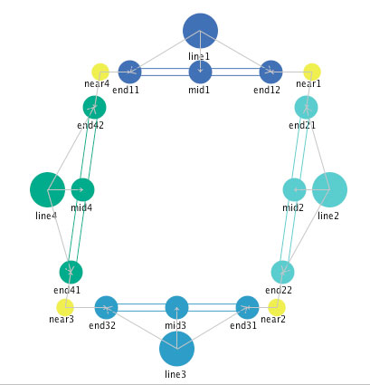
Figure 20: The definition of a quadrilateral.
Like the "pivot" above, the four "near" mediators help to specify this quadrilateral, but there are no other mediators that constrain the angles that each of these corners make. So there are any number of different stable forms that this quadrilateral can take. Four of them are shown in Figure 21.
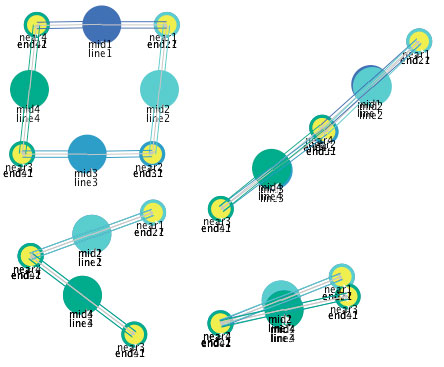
Figure 21: Four of an infinite number of stable states of
the quadrilateral.
If we add invisible line segments, as we did in the case of the pivot above, we can then constrain the shape so that it has fewer stable states. Figure 22 shows a representation of a square.
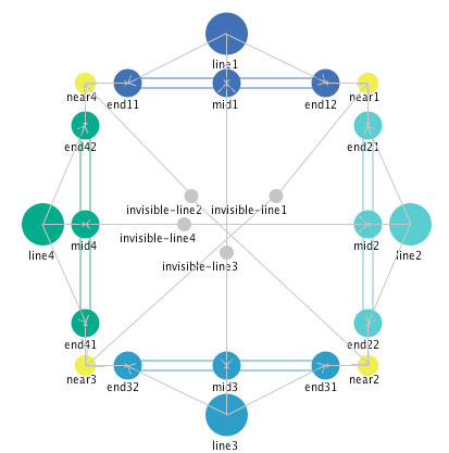
Figure 22: A definition of a square.
When these invisible line segments all operate as mediators, the resulting state will be a square, even if it is rotated at some angle, as shown in Figure 23.
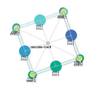
Figure 23: The results of the operation of the mediators in the
definition of a square.
References
Levin, J. A. (2009). Landmark representation and dynamic mediation. [ Available at http://pages.ucsd.edu/~jalevin/landmark-mediation ]
Wilensky, U. (1999). NetLogo. http://ccl.northwestern.edu/netlogo. Evanston, IL: Center for Connected Learning and Computer-Based Modeling, Northwestern University.